Monday, September 25, 2006

OpenRT—Realtime RenderMan Ray-Tracing OpenGL

OpenRT is a realtime ray tracing rendering engine and API. It is designed as powerful as RenderMan by offering all features of ray tracing. And as similar as OpenGL, while as possible. It is RenderMan-like for shader writer and OpenGL-like for application programmers. OpenRT in contrast of OpenGL, supports no immediate mode. This means that every geometry you want to display has to be contained in an OpenRT object. This object has to be instantiated and can then be rendered. This is because ray tracing uses a global approach, not as raster dealing triangles independently.

A non-commercial version of OpenRT can be download from here. But it supports no cluster. And so a dual-core Itanium2 might be a not-so-not-decent processor to run it as a single node. IMHO, OpenRT is designed to run over cluster other than super powerful single node, at least talk against today's computer. I tried the commercial version on my so humble cluster of old old pentium 4s, yet what makes me love it most is that the speedup is so so linear to the number of nodes due to the properties of ray tracing algorithm.

Imagine, realtime RenderMan! Leading digital effects houses and computer graphics specialists use RenderMan and every movie nominated for a Visual Effects Oscar in the last 10 years relied somewhat on RenderMan.

The commercial version is around £40,000 for 16 nodes Itanium2 (IA64). So you see, OpenRT is by no means of Open Source project, only but puns OpenGL.

Ray Tracing vs. Raster Graphics

The rendering technique—ray tracing has reached the stage where it is feasible that it will take over from raster graphics in the near future for interactive simulation/gaming and other application domains. Ray tracing is the act of tracing the trajectory of a ray from one point to another to determine if anything is hit and the distance to the nearest hit point. In fact, ray-tracing techniques can achieve the exact same results as raster-based techniques (including all the approximations and tricks that raster solutions typically require); however, it does not work the other way round.


The primary differentiating factor between raster- and ray tracing approaches is that a ray tracing approach enables one to solve a global problem, while a raster-based approach seeks to achieve similar results by solving a local problem.

Raster graphics attempts to render an image efficiently by making certain convenient assumptions. In particular, it treats triangles as if each triangle is entirely independent of every other triangle. There is a concept of the current state and the current triangle. This is the Graphics Processing Unit's (GPU) view of the entire world; it has no idea if or what comes next. In general, due to the way that raster systems work, they process every pixel of every submitted triangle to determine the final image that needs to be displayed. So raster graphics performance scales strongly with the number of triangles and pixels that have to be processed for a given image, so cost scales strongly linearly with viewport size and overall scene complexity.

Because ray tracing takes a global approach, the natural interface to it is different that that used with raster graphics. Recall that raster graphics use an “immediate mode” interface, and is only aware of a current state and a current primitive at any point in time. Ray tracing, on the other hand, needs a “retained mode” interface where random access to the whole scene is required, and when a visible triangle is determined, a specific shader needs to be invoked on demand. However, the really exciting news is how the ray tracing workload scales. It is strongly effected by the number of rays shot in a scene and weakly effected by the complexity of the scene! Ray tracing scales linearly with the number of rays shot and only logarithmically with the complexity of the scene. For a fixed resolution image, the cost of raster graphics doubles (roughly) as the complexity of the scene doubles; for ray tracing, you would have to increase the viewed scene complexity by 10 times to double the cost. Here we emphasize viewed scene for the ray tracing is not so much overall scene complexity dependent, but dependent upon the visible complexity of the scene. Another amazing fact of ray tracing is that its performance scales linearly with the number of CPUs ( with today's raster oriented graphics accelerators ). And measured linear performance scales up to 128 CPUs (3.2GHz Pentium 4).


Tuesday, September 12, 2006

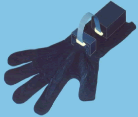
5DT Data Glove Successfully Connected to Linux Cluster CAVE Demo

The 5DT Data Glove 16 (right hand) now successfully connected to our Linux cluster city demo, a four-screen CAVE demo. As simple as using pre-defined gesture, index finger, for example to indicate turn right, you can program the gesture as complicated as you want while using raw data instead of pre-defined gestures.

The 5DT Data Glove 16 measures finger flexure as well as the abduction between the fingers. Finger flexure is measured at two places (1st joint/knuckle, 2nd joint) on each finger. The glove consists of a lycra glove with embedded fibre optic sensors. The 5DT Data Glove 16 connects to a 9-pin RS232 serial port (DB9 connector) via the interface cable.

The 5DT Data Glove Driver provides access to the 5DT range of data gloves at an intermediate level. The Linux version is provided in form of a C/C++ header file (fglove.h), and a dynamic library file (libfglove.so). The API is free for both Windows and Linux.

There are 16 pre-defined gestures, i.e., 0 for fist and 15 for flat hand, etc.

Friday, September 01, 2006

Capture Muscle's Subtle Movement

During dynamic activities, the surface of the human body moves in many subtle but visually significant ways: bending, bulging, jiggling, and stretching, according to this SIGGRAGH 2006 paper. They used around 350 small markers (diameter 3.0mm with hemispherical shape) and commercial motion capture system from Vicon (12 cameras with 4 megapixel resolution capture at rate 120 frame/sec). The average distance between two neighbouring markers was 4-5mm. In order to get high precise, they located the cameras close to the subject, so the capture region was approximately 2m by 2m by 2.5m. Two cameras were set looking up rather than down to capture markers facing toward ground.

If you interested, you can downloaded the movie to see how this method work. And read the whole paper for more details.